
CT’s in Residential Solar & Battery Systems: Diagnostic Steps for Electricians
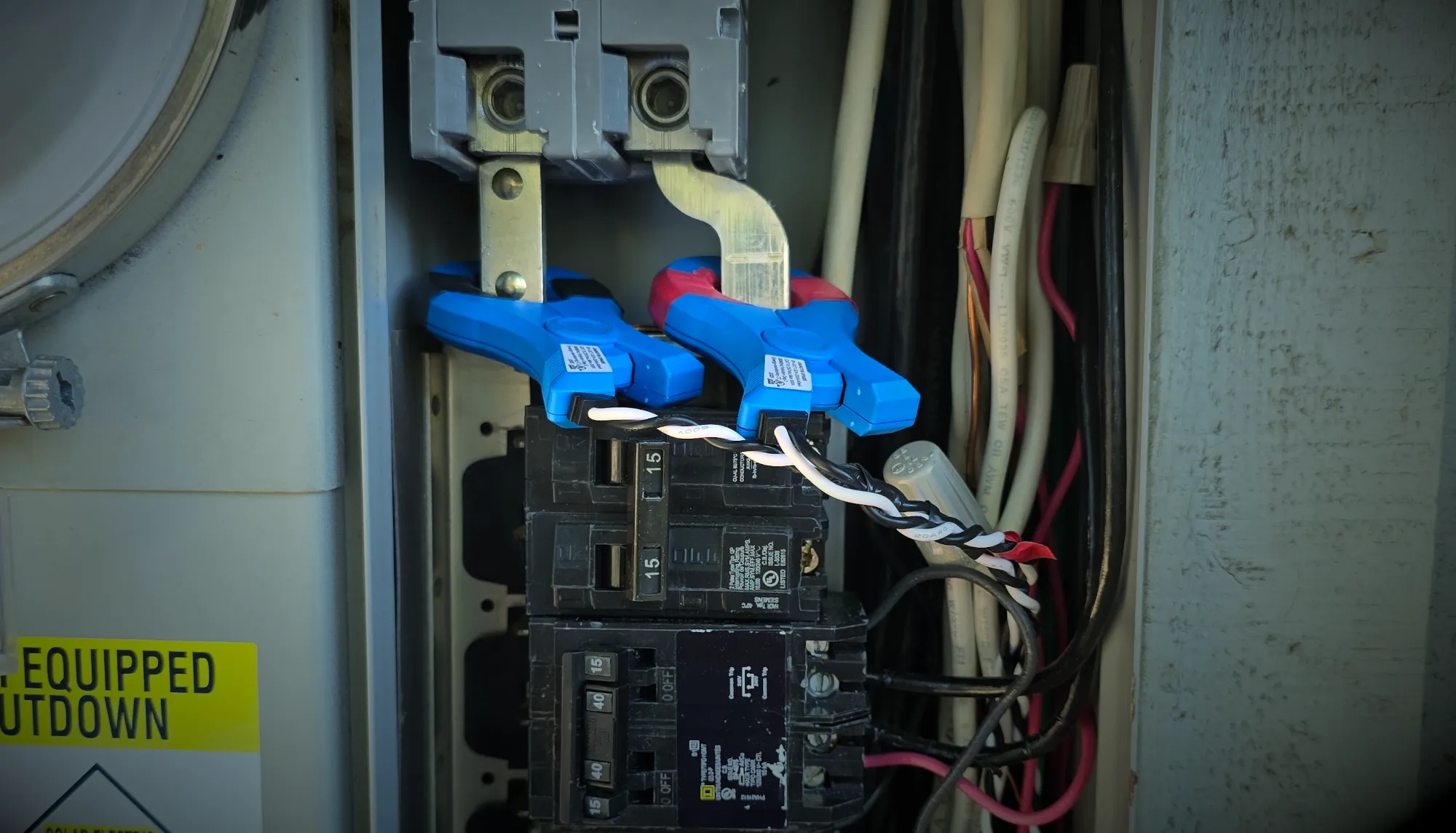
Current transformers, usually called CT’s, are one of the most important and most overlooked parts of a residential solar or battery system. When they are installed correctly, they let the inverter, battery, gateway, or monitoring platform understand what is happening at the service, solar production, battery output, backup loads, and sometimes additional generation sources.
When they are installed incorrectly, the whole system can look confused. You may see negative solar production, battery charging when it should be discharging, import/export numbers that do not match the utility meter, flickering or erratic power flow screens, or a homeowner who swears the system has not worked right since the install.
For electricians working on solar and battery systems in the Sacramento area, CT troubleshooting is one of those skills that separates guessing from actually diagnosing. The good news is that most CT problems can be found with a meter, an amp clamp, a basic understanding of phasing, and a methodical process.
What CT’s Actually Do in a Solar and Battery System
A CT measures current on a conductor without being installed in series with the circuit. In residential solar and battery systems, CT’s are commonly used to measure:
- Site import and export at the service
- Solar production from one or more inverters
- Battery charge and discharge behavior
- Non-backup loads
- Additional generation sources
The system uses that current reading, along with voltage reference, to determine power flow. That is why CT direction, CT location, and phase relationship all matter. A CT can be physically closed around the correct wire and still give the system bad information if it is facing the wrong direction, assigned to the wrong phase, or paired with the wrong voltage reference.
Start With the Site CT’s
Site CT’s are usually the first place I look when a system has confusing power flow data. These CT’s tell the system whether the home is importing from the grid or exporting back to the utility. If the site CT’s are wrong, everything downstream can appear wrong too.
A good first check is simple: compare the system’s power flow screen to the utility meter. If the app says the home is exporting 4 kW but the utility meter shows the home is importing, do not keep chasing software settings. Start verifying CT placement and direction.
Check Whether the Power Flow Matches the Utility Meter
With the system operating normally, compare the kW shown in the app or installer portal against the utility meter. The numbers do not have to match perfectly, but the direction should make sense. If the utility meter shows import, the system should not be showing export. If solar is producing heavily and loads are low, export may be expected.
For a cleaner test, shut off generation sources and look at the site reading with normal house loads running. With solar and batteries off, the site should generally show import. If it shows export with all generation off, that is a major clue that the CT direction, configuration, or phase assignment is wrong.
Verify CT Direction
CT direction matters. Most split-core CT’s have an arrow or label indicating the intended direction of power flow. Depending on the manufacturer, that arrow may point toward the grid, toward the load, or follow a specific instruction in the installation manual. Do not assume every brand does it the same way.
A practical field check is to turn off all generation sources and confirm the site meter shows import. If the system shows export under that condition, the CT’s may be reversed, incorrectly configured, or assigned to the wrong meter role.
Confirm the CT’s Are Capturing All Loads
Site CT’s need to be installed where they actually see the whole site. If a load is upstream of the site CT’s, the system will not know that load exists. In a battery system, this can cause incorrect backup behavior, incorrect self-consumption behavior, or monitoring numbers that never match the utility meter.
This is especially important on services with line-side taps, multiple panels, subpanels, meter-main combos, backup load panels, or limited access to bussing. Before assuming a software issue, verify that all conductors feeding the loads you intend to measure are actually downstream of the site CT’s.
Bundled Conductors and Tight Service Equipment
Some of the hardest CT problems happen when there is not enough room to clamp around individual conductors cleanly. In crowded service equipment, installers sometimes bundle conductors through a CT to work around limited access.
Bundling can be valid in some situations, but only if it is done correctly. Conductors passing through the same CT need to be on the same phase and oriented the same direction. If opposing current paths are passed through the same CT, the readings can cancel each other out or give a misleading value.
When troubleshooting bundled CT’s, check these items:
- Are all conductors through the CT on the same phase?
- Are they all passing through the CT in the same direction?
- Are any neutral or opposite-phase conductors accidentally included?
- Are the CT jaws fully closed?
- Is the CT handle or latch being pushed open by the dead front?
That last one is easy to miss. I have seen CT’s that looked closed until the panel cover went back on. If the dead front presses on the CT and cracks it open even slightly, you can end up chasing a problem that only exists when the equipment is fully assembled.
Use an Amp Clamp to Verify Magnitude
Once the direction and location look right, verify the actual current. Use an amp clamp on the same conductor the CT is measuring and compare the expected kW against what the monitoring platform is showing.
For a quick single-phase estimate, volts multiplied by amps gives you apparent power. On a 240V split-phase system, you need to be mindful of which phase you are measuring and how the monitoring system is calculating total power. The goal is not always to get a perfect number in the field, but you should be close enough to tell whether the CT is reading the correct magnitude.
If the amp clamp shows a large load but the system shows little or no power, look for a loose CT connection, a CT assigned to the wrong meter, an open CT jaw, a failed CT, or a configuration issue.
Phasing: The Part That Gets People in Trouble
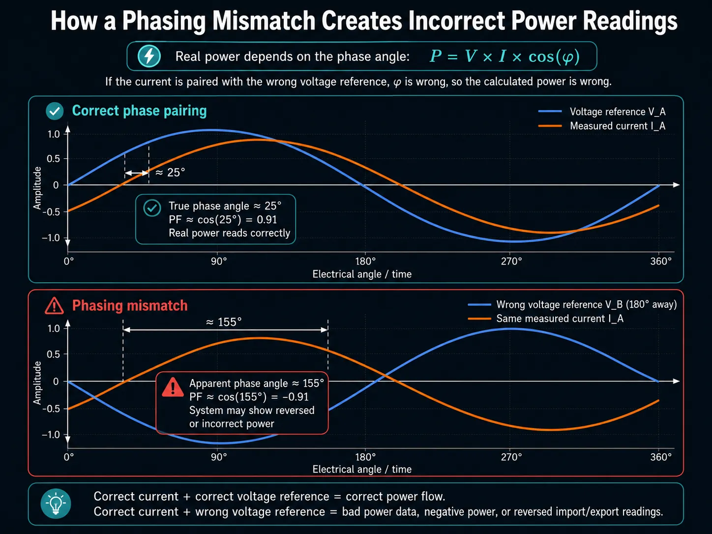
Phasing is one of the biggest reasons CT readings look wrong even when the CT is physically installed on the right conductor. The system is not just measuring current. It is comparing that current to a voltage reference. If the CT is on one phase but the meter thinks it is associated with the other phase, the calculated power can be wrong.
This can show up as incorrect import/export direction, poor power factor, negative production, or readings that change in a way that does not make sense as loads turn on and off.
When diagnosing phasing, confirm:
- Voltage from L1 to neutral and L2 to neutral
- Voltage from L1 to L2
- Continuity or conductor identification where needed
- Which phase each CT is physically clamped around
- Which CT port corresponds to which phase in that specific meter
Do not rely only on wire color, especially in older equipment, retrofits, or panels that have been modified over time. Verify it.
Remote Meters: CT Ports Matter
Remote meters add another layer because the CT ports are often phase-specific. For example, Tesla’s documentation for the Tesla Remote Energy Meter shows L1 using CT1 and L2 using CT2 or CT3 for site CT’s. Tesla’s Neurio meter documentation lists L1 on CT1 or CT4 and L2 on CT2 or CT3. That means you cannot just plug CT’s into random open ports and expect the software to sort it out. Follow the meter-specific documentation. Tesla Remote Energy Meter CT installation guide and Tesla Neurio Remote Energy Meter CT installation guide.
This is especially important when monitoring additional solar, non-backup loads, or generation sources that are not passing through the main gateway or battery inverter. The reference voltage and CT phase have to agree, or the reading may be technically measured but mathematically wrong.
Additional Generation Sources
Additional generation sources can complicate a battery system quickly. This may include an existing solar inverter, an added solar system, or another production source that needs to be monitored separately.
For generation CT’s, the reading generally should not be negative during normal production. If the sun is out, the inverter is producing, and the system shows negative generation, start with CT direction and configuration.
Also check whether the meter is configured correctly. Some platforms have settings for using one CT to represent both legs of a 240V inverter output. For example, a “CT x 2” style setting may be used when a single CT is installed to meter a 240V source. If you have one CT on each phase, that setting may need to be off. If this setting is wrong, the production value can be doubled, halved, or just plain misleading.
Power Factor Can Point You Toward the Problem
Power factor is a useful clue when CT readings do not make sense. A very poor or strange power factor reading may suggest the CT is associated with the wrong voltage phase, installed backward, or measuring something different than the system thinks it is measuring.
In the real world, you do not need to turn every CT service call into an engineering lecture. But if the real power value looks wrong while the current magnitude seems believable, start thinking about the relationship between voltage, current, phase angle, and CT assignment.
In other words: the CT may be reading current, but the system may be using the wrong voltage reference to turn that current into a power value.
A Simple CT Diagnostic Process
When I am troubleshooting CT’s on a residential solar or battery system, I like to work in a simple order:
- Compare the system power flow screen to the utility meter.
- Turn off solar and battery generation sources when possible.
- Confirm the site reading shows import with normal house loads running.
- Verify CT direction.
- Confirm the CT’s are installed around the correct conductors.
- Check that all intended loads are downstream of the site CT’s.
- Use an amp clamp to verify current magnitude.
- Verify phasing with voltage checks and conductor tracing where needed.
- Confirm CT port assignment and meter configuration.
- Reassemble the equipment and confirm the dead front is not disturbing the CT’s.
That process catches the majority of CT-related problems without jumping straight into parts replacement or software blame.
Common Symptoms of CT Problems
CT issues can show up in a lot of different ways. Some of the more common symptoms include:
- Solar production showing as negative
- Battery charging or discharging at the wrong time
- Home consumption that looks too high or too low
- Import/export readings that do not match the utility meter
- Erratic power flow animation in the app
- Production numbers that appear doubled or cut in half
- Power factor readings that look suspicious
- Monitoring that changes after the dead front is installed
These symptoms do not automatically prove a CT issue, but they are enough reason to slow down and verify the basics.
Why This Matters for Homeowners
For homeowners, bad CT readings can make a working solar or battery system look broken. They can also make a broken system look like it is working. Either way, the homeowner is left trying to interpret an app that may not be telling the truth.
This matters even more with battery systems, time-of-use rates, backup panels, and utility bill concerns. If the system does not know what the home is importing, exporting, producing, or consuming, then the homeowner cannot make good decisions based on the data.
That is why CT verification is part of a proper solar and battery diagnostic process. Monitoring data is useful, but only if the underlying measurements are correct.
Solar and Battery Diagnostics in the Sacramento Area
McKnight Solar Diagnostics provides solar and battery troubleshooting, inspection, performance verification, and monitoring support throughout the Sacramento region. If your system’s app does not match your utility meter, your battery behavior seems wrong, or your production numbers do not make sense, the issue may not be the panels or the battery. It may be the way the system is measuring power.
We help homeowners, realtors, and property professionals understand what is actually happening with existing solar and battery systems before unnecessary repairs or replacements are recommended.
Learn more about our solar diagnostics and repair services, solar inspection services, and solar system optimization services.
Leave a Reply